
During firing in tunnel kiln, bricks and tiles go through heating‑up, holding and cooling stages. The tunnel‑kiln system must satisfy all technical parameters to guarantee normal heating, holding and cooling of green bodies.
Also called working flow, the working system of tunnel kiln refers to the gas conveying system including gas flow path and relevant thermal‑equipment configuration. It is designed based on firing regime to realize stable firing conditions.
Raw materials for brick‑tile production vary greatly with different firing properties, hence system configurations differ for different raw materials and products. However, all tunnel kilns share the same fundamental working‑system framework, consisting of kiln ventilation system (flue‑gas exhaust, waste‑heat extraction, cold‑air supply, kiln‑bottom pressure‑balancing system), fuel combustion system, kiln‑car handling system and measurement‑control system.
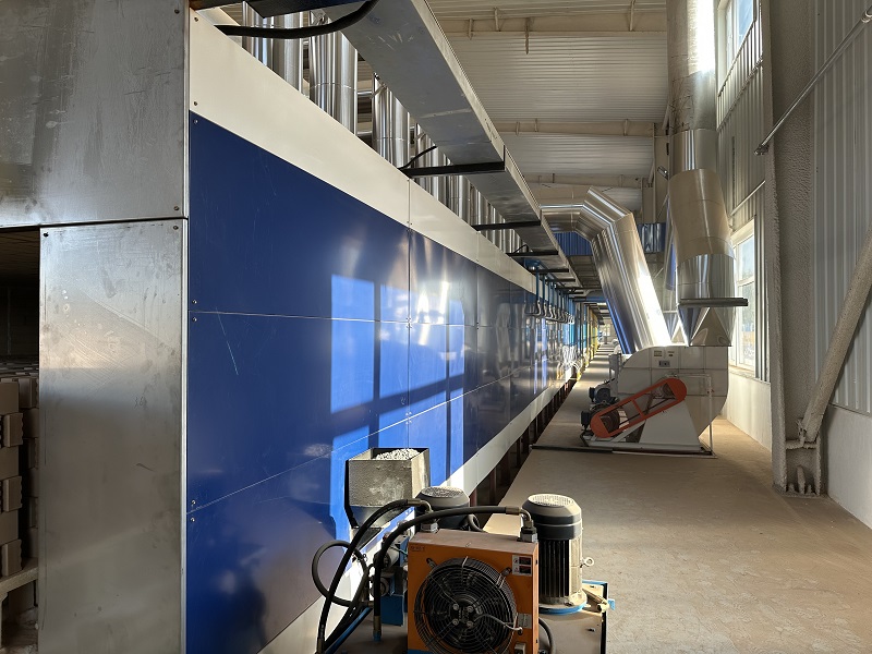
Tunnel‑kiln ventilation system mainly covers flue‑gas exhaust system, cold‑air supply system, waste‑heat extraction system and kiln‑bottom pressure‑balancing system; some kilns are also equipped with circulating‑air system.
The ventilation system guides gas flow direction, ensures even air distribution among ware stacks, supplies combustion air, discharges flue gas, stabilizes temperature‑pressure regimes and guarantees normal firing operation.
Located in preheating zone, the exhaust system comprises exhaust openings, branch flues, main flue, dampers and exhaust fan. It discharges low‑temperature high‑humidity flue gas from preheating zone. Hot flue gas passes through exhaust openings on side walls or roof. Dampers near openings regulate exhaust volume. Then flue gas flows through branch flues into main flue, and is drawn out of kiln by exhaust fan installed on main flue.
Cross‑section dimensions of exhaust openings, branch flues and main flue shall be calculated in detail according to flue‑gas output from fuel combustion. Fan selection shall also match exhaust gas volume.
Proper selection of exhaust fan influences firing output, product quality and production cost. When selecting exhaust fan, calculate total pressure for system resistance and required air volume, then choose high‑performance fan model with flat characteristic curve and wide working range. Installation position, mounting angle and cost shall also be considered.
Located in cooling zone, air‑supply system consists of cooling fans, air nozzles and control dampers. It delivers cooling air to cool down hot finished bricks.
Air‑supply volume is determined by air demand for fuel combustion in firing zone, waste‑heat volume calculated from thermal balance of cooling zone and air‑leakage loss in cooling zone. The sum equals practical air volume, which shall be converted into standard air volume for fan‑model selection. Either centrifugal fan or axial‑flow fan can be adopted according to kiln layout, structure and firing requirements.
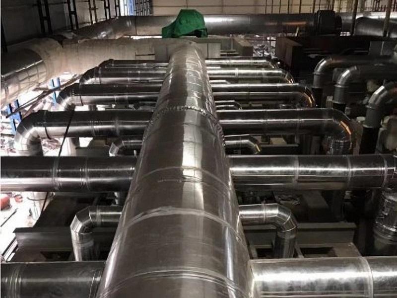
Waste‑heat extraction system operates both in cooling zone and preheating zone. Clean hot air is extracted from cooling zone (heat recovered from cooling bricks); high‑temperature flue gas is extracted from preheating zone.
This system includes fans, pipelines, in‑kiln air outlets and dampers. Heat is extracted from different positions to satisfy practical firing requirements. Heat‑recovery volume and air flow are adjusted by damper opening, and fan model is determined via thermal calculation.
The kiln‑bottom pressure‑balancing system equalizes pressure between kiln‑car bottom and kiln interior. Where negative pressure prevails inside kiln, negative pressure is maintained under kiln cars; where positive pressure prevails inside kiln, positive pressure is also maintained under kiln cars. It prevents hot kiln gas leaking downward as well as cold ambient air infiltrating in through sand‑seal gaps.
Commissioning of this system is critical. Pressure under kiln cars must be adjusted to match kiln‑interior pressure. Excessive pressure difference will disable balancing function and cause adverse effects.
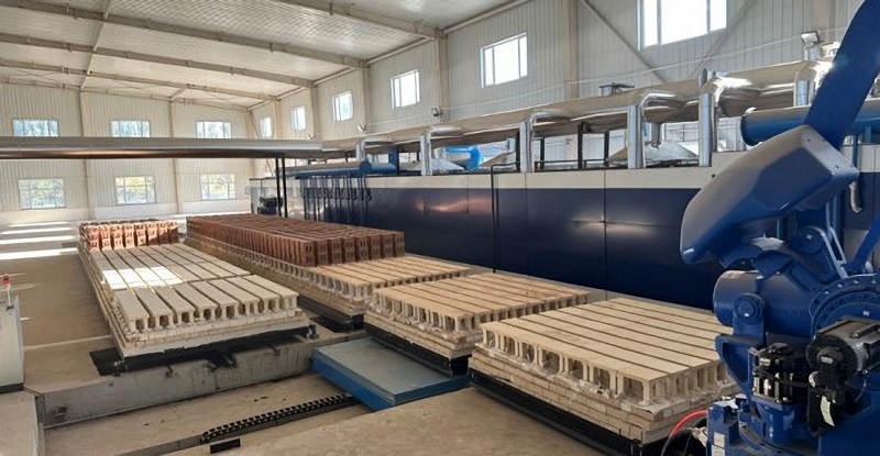
Kiln cars move forward intermittently inside tunnel kiln during firing. The kiln‑car handling system realizes transportation of kiln cars inside kiln and along process lines. It includes electric transfer car, hydraulic pusher, return‑line tractor, step feeder, exit puller and kiln doors.
Electric ferry car is essential for kiln‑car transportation in workshop. It realizes transverse movement and direction change of kiln cars. It transfers green‑body‑loaded kiln cars from return line to drying chamber or tunnel kiln, and delivers finished‑product kiln cars from kiln exit to return line.
Hydraulic pusher provides driving force for kiln‑car advance inside kiln. Oil pump drives piston inside hydraulic cylinder to perform linear motion, and the piston pushes kiln cars forward.
Installed on return line, return‑line tractor drives kiln‑car circulation on return track. It consists of winch and travelling trolley. Winch drives trolley moving on track, and the trolley pushes kiln cars.
Step pusher is arranged at setting station of return line for precise kiln‑car positioning. After one stack of green bodies is set by manual workers or setting machine, step feeder moves kiln car forward by one‑stack distance. Without step pusher, empty kiln cars cannot be accurately positioned for setting.
Kiln car tractor pulls out the last fired kiln car from cooling‑zone exit to vacate position for new incoming kiln car. After being pulled out, the firing process for this batch of bricks is completed. Driven by electric motor, its rated power is determined by total weight of kiln car plus loaded bricks. One exit puller is installed under kiln‑car track inside each tunnel kiln.
Kiln doors are fitted at kiln inlet and outlet to isolate kiln interior from ambient environment, preventing cold‑air infiltration and hot‑gas leakage. Doors are lifted for car entry and lowered after car enters kiln. Reliable sealing performance is required between door and kiln wall /roof after closing.
Tunnel‑kiln control system includes two modules: temperature‑pressure monitoring & control, and kiln‑car handling‑system control.
Temperature and pressure sensors are mounted on kiln roof and side walls. Measured data is transmitted to computer. Automatic or manual regulating devices are installed on ventilation system. When measured temperature /pressure deviates largely from design value, computer sends commands to adjust air flow via automatic actuators; or operator adjust manual dampers to modify kiln air flow.
For kiln‑car handling‑system control, control switches are fitted on each piece of equipment. Relays control sequence and working duration of each device to realize automatic operation. Another solution is zoning control: automatic control within each zone, and manual coordination between different zones.
