
The rationality of system configuration, kiln body structure and operational conditions of a tunnel kiln exert significant impacts on product quality, output, fuel consumption and service life of the kiln.
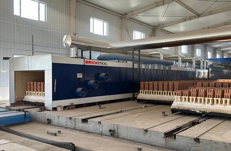
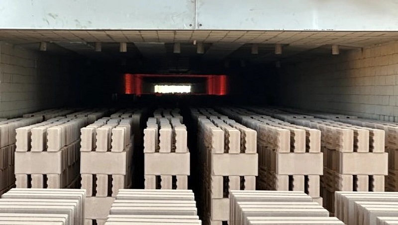
A tunnel kiln is a counter‑current thermal equipment. Along its longitudinal direction, it is divided into preheating zone, firing zone and cooling zone. Wares and hot gas flow in opposite directions, so the wares complete preheating, firing and cooling successively in these three zones.
Kiln doors are installed at both ends of the tunnel kiln. At regular intervals, one kiln car loaded with green bricks is pushed into the kiln, meanwhile one kiln car carrying finished bricks and tiles is pushed out.
After entering the preheating zone, green bodies are first heated by flue gas from the firing zone. Then they move to the firing zone, where heat released from fuel combustion heats the green bodies to target firing temperature. After a certain holding period, stable finished products are formed.
Flue gas is discharged out of kiln through exhaust openings, flues, fans or chimneys in the preheating zone.
Fired wares go into the cooling zone and transfer heat to incoming cold air. The finished wares get cooled and exit the kiln. Part of the heated air is sent to firing zone as combustion‑supporting air; the rest is extracted for waste‑heat recovery.
Simply speaking, the firing process in tunnel kiln consists of fuel combustion as well as heat‑moisture exchange between green bodies and gas. Heat from fuel combustion raises kiln temperature to the required firing level. At firing temperature, a series of physical and chemical reactions take place inside green bodies. Through these changes, green bodies are sintered into finished bricks with sufficient strength, durability and compliance with building requirements.
Guided by thermal engineering fundamentals, the working‑system design of tunnel kiln aims to formulate and realize proper firing regimes for specific raw materials and products. Firing regime of tunnel kiln includes temperature regime and pressure regime.
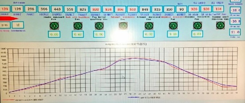
It refers to the temperature profile measured by thermocouples mounted on kiln roof or side walls along kiln length, as shown in Figure 1. At low‑temperature stage, it approximates gas temperature; at high‑temperature stage, it approximates ware temperature.
A theoretical temperature profile is provided in kiln design under ideal conditions for given raw materials and products. In actual production, due to equipment differences and raw‑material fluctuation, the practical firing curve deviates from theoretical value. Guided by theoretical profile and firing rules, operators shall adjust to obtain the optimal firing curve according to practical raw materials, equipment and product specifications.
It generally means static‑pressure distribution along kiln length. Pressure‑regime control is closely related to temperature‑regime control, and its objective is to guarantee the temperature regime.
The cooling zone keeps positive pressure, while the preheating zone maintains negative pressure under suction of chimney or exhaust fan. Between positive‑pressure zone and negative‑pressure zone, there exists a car position where static pressure equals zero, defined as zero‑pressure point.
In practical production, the zero‑pressure point is normally kept between preheating zone and firing zone to maintain slight positive pressure within firing zone, which benefits stable operation.
If zero‑pressure point shifts to cooling zone, firing zone will be under negative pressure. Large amount of cold air will leak in from kiln bottom and increase vertical temperature difference.
On the contrary, if zero‑pressure point moves into preheating zone, firing zone will bear excessive positive pressure. High‑temperature gas may leak downward and damage kiln cars.
Due to variable operating conditions, zero‑pressure point tends to drift, and it should be readjusted back to target position once deviation occurs.
Zero‑pressure point is adjusted by dampers of exhaust outlets and waste‑heat outlets. Increasing waste‑heat extraction will shift zero‑pressure point towards cooling zone; increasing exhaust capacity of flue dampers will shift zero‑pressure point towards preheating zone.
Besides zero‑pressure‑point position, operators shall also control absolute values of positive pressure in cooling zone and negative pressure in preheating zone, i.e. slope of pressure profile. A gentle, flat pressure profile (so‑called low‑pressure operation) is preferred to minimize gas leakage.
Nevertheless, high suction and high‑temperature operation are often adopted for higher output. Under such circumstances, static‑pressure balancing measures at kiln bottom shall be implemented to reduce inward and outward gas leakage.
